AR Series
This guide is designed to assist first-time users to connect and operate the AR- series radar sensor. It is strongly recommended to carefully read and review the entire AR-series User Manual as well as the MASS User Guide (if purchased) for safe and proper operation of the sensor.
Connection, Configuration and software
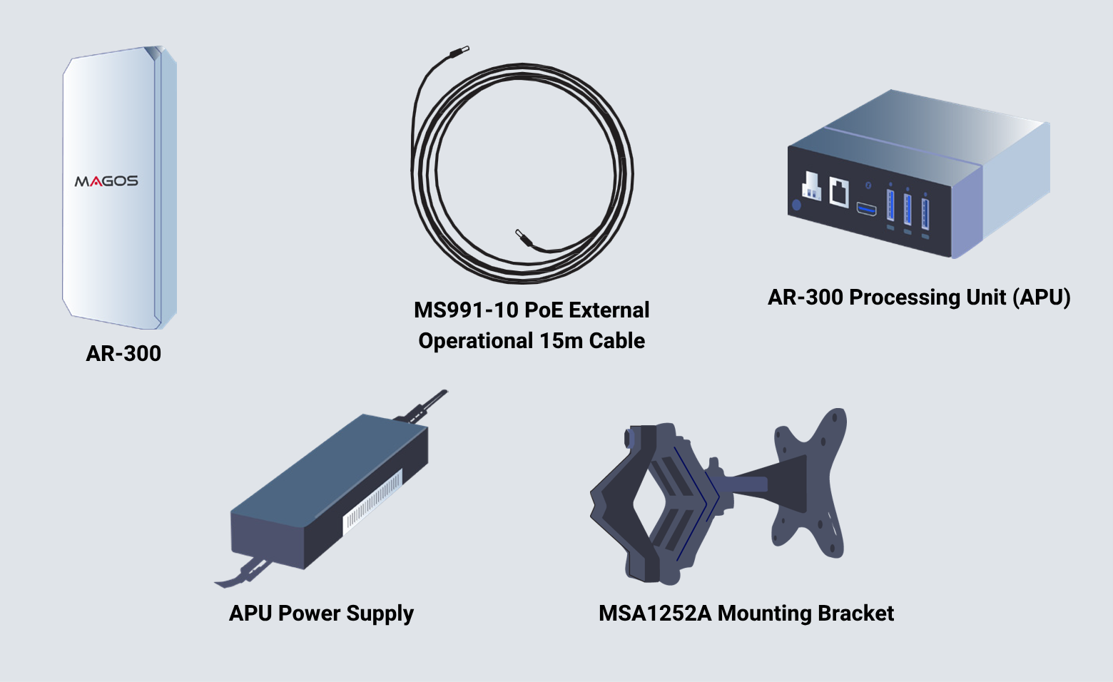
Visually Inspect The Contents of The Package
Ensure that the package contents match your order and that no physical damage has occurred to any of the supplied products during transportation. AR Sensor kits include an external processing unit.
Connect The Cable to The Sensor
Follow the mating guide key on both sides as illustrated:
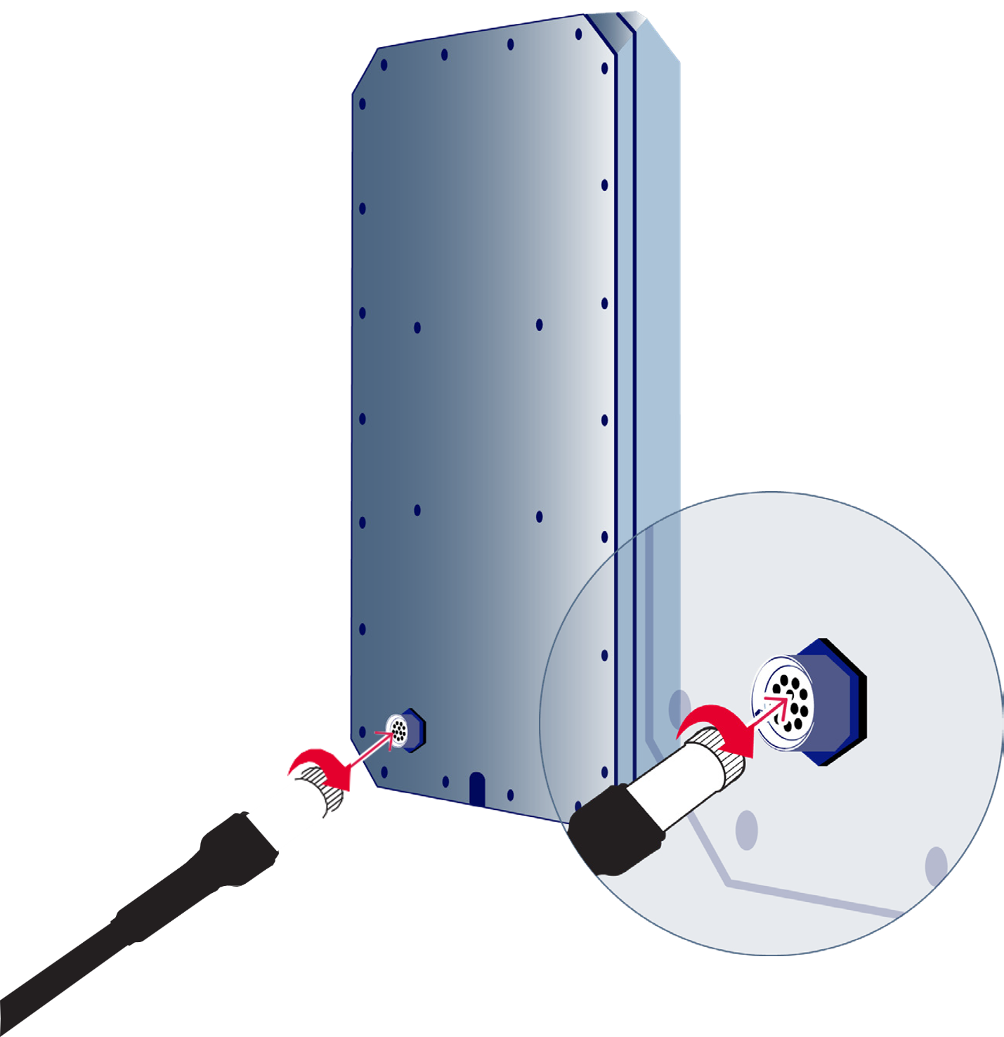
Warranty does not cover water damage caused to the connector. In order to avoid such damage, the cap must be attached whenever a cable is not plugged in whether using the cable or the the cap enusre that they are securely connected by twisting them until firmly locked.
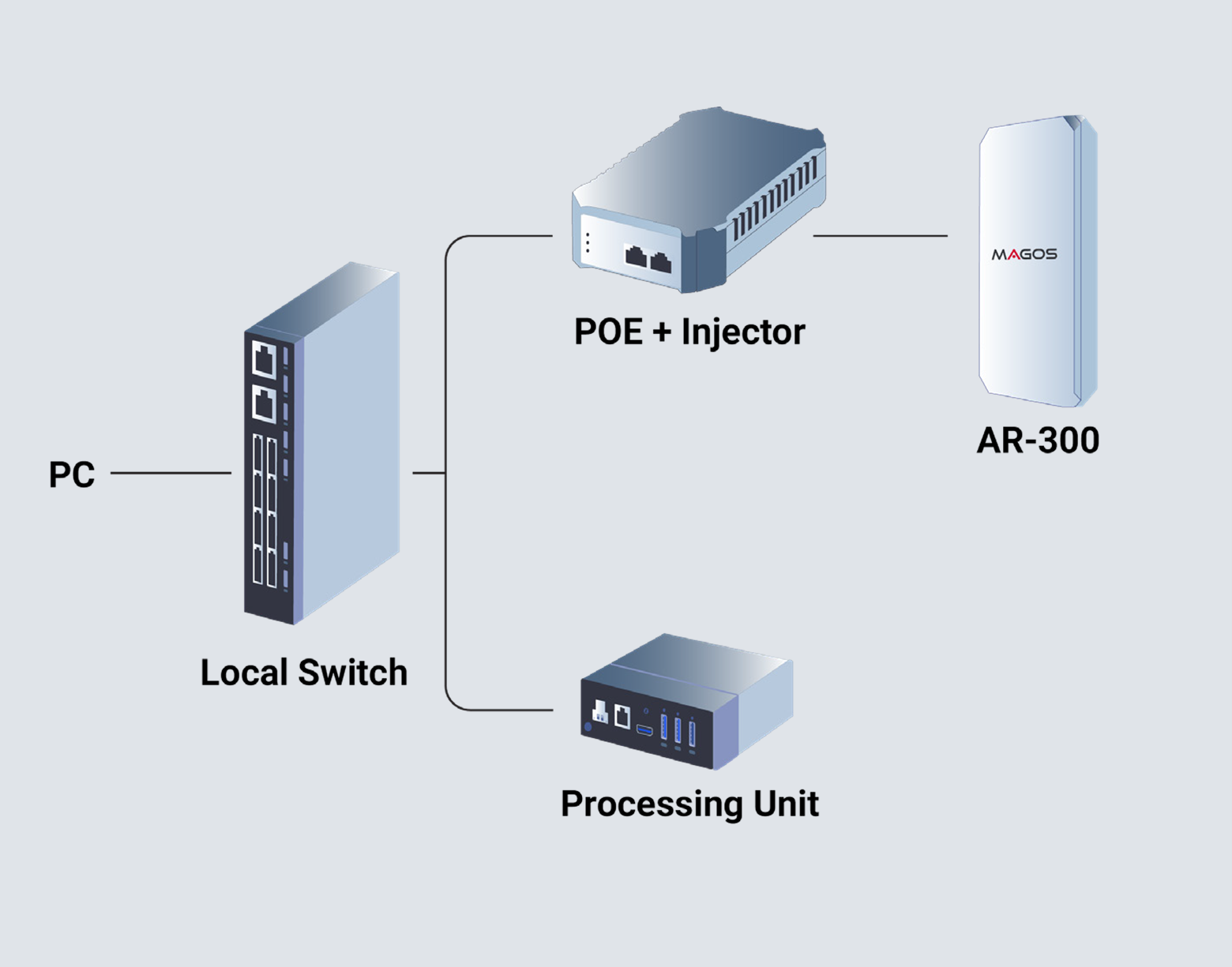
Connect The Units To The Network
- Use a PC or laptop running windows 7 OS or higher.
- Connect the AR-300 cable to a POE++ Type 3 POE injector or switch (not included).
- To power the APU, use a standard “Mickey-Mouse” (not included) power cord for the APU power supply.
- Connect both injector and the APU to a standard local network switch using standard network cables (not included).
Download Required Software
Visit our partner's portal. You will be required to login using the credentials you have received from help@ magosys.com. Browse to the “Software” tab and download the Radar Manager Application as well as the MASS application (if purchased) from the “Downloads” tab.
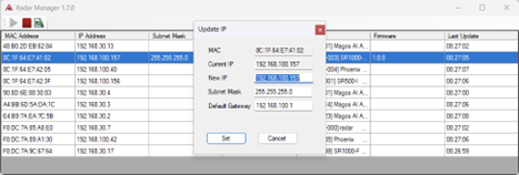
Assign IP Address to the Sensor
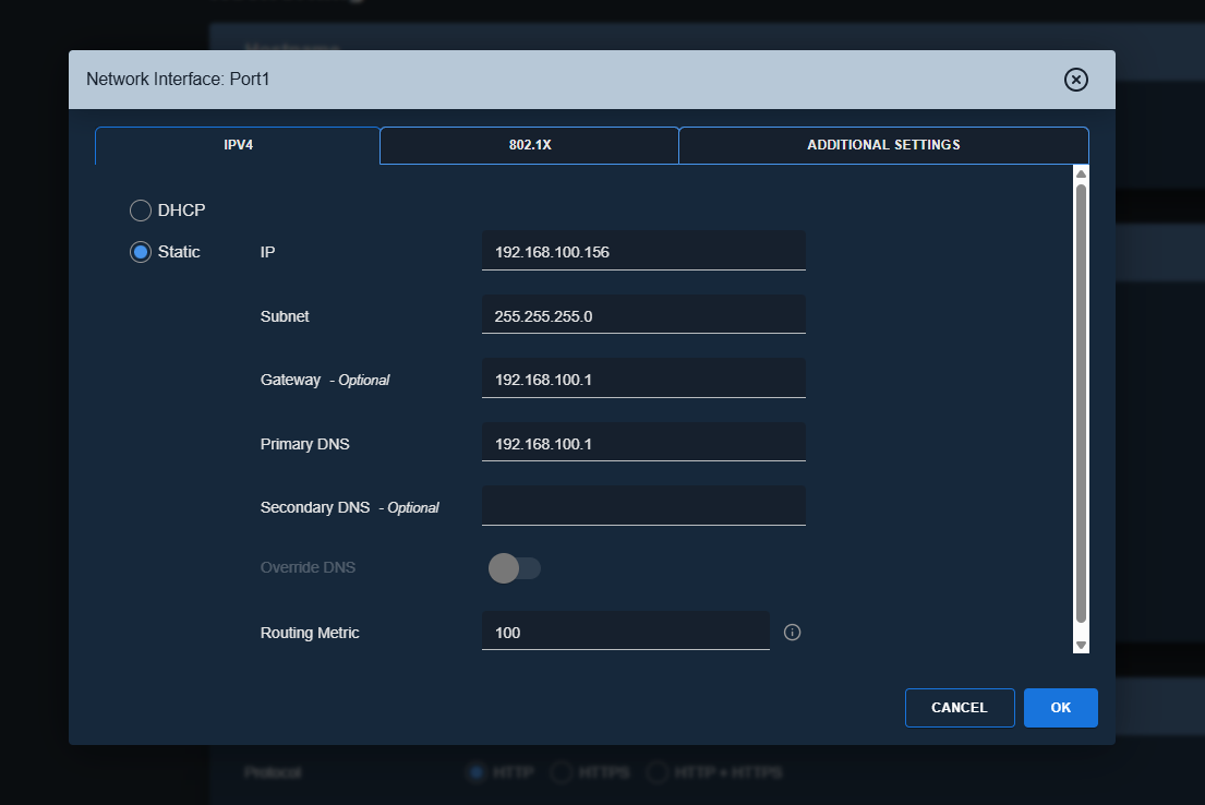
Use the radar manager application to assign a new IP address to the sensor and processing unit: To change IP, right click on the current IP address reported, and choose “Assign IP”. Enter the new desired IP address, subnet mask and gateway.
The computer and the sensor must be in the same subnet mask, otherwise they will not communicate. Default IP address for the sensor is 192.168.40.50 and for the processing unit: 192.168.40.60.
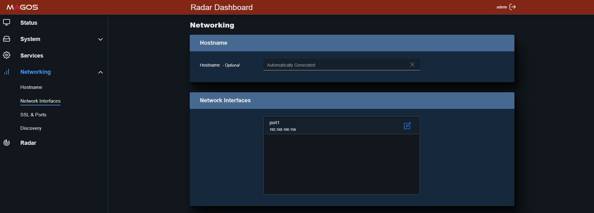
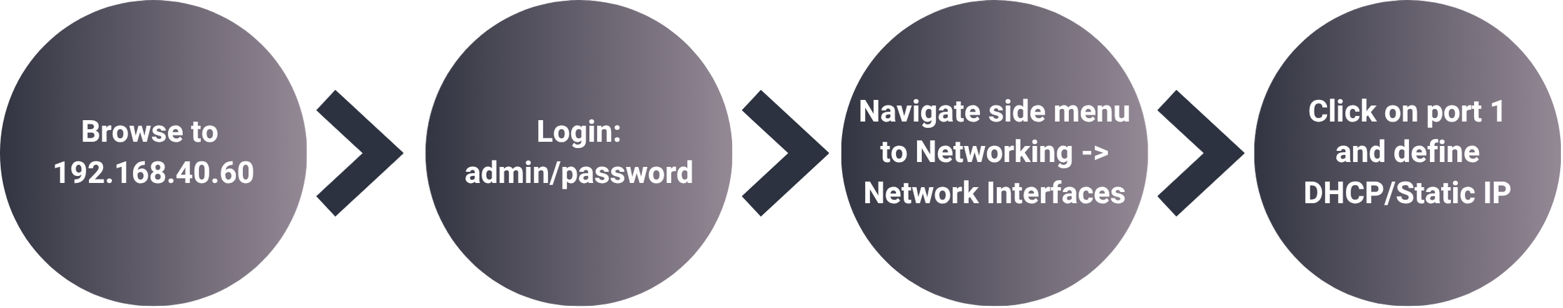
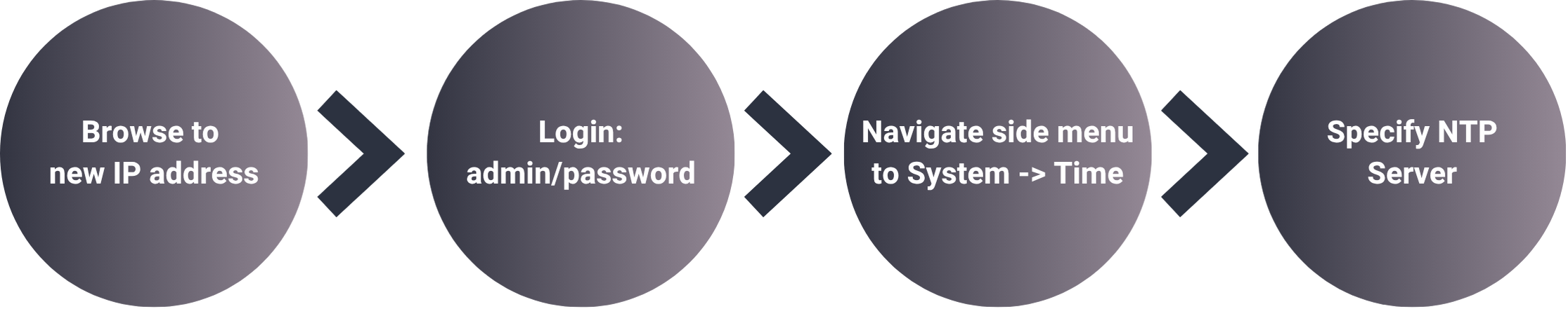
Alternatively, you can change IP address via the web-based dashboard. Use any browser, type 192.168.40.50 or 192.168.40.60 in the browser address bar. Default username is: admin, default password is: password
Assign NTP Server and Connect Sensor to Processing Unit
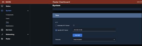
Setting up an NTP server for the radar and the API is essential to ensure they operate properly. Via the web dashboard, set the local NTP server address in the System tab -> Time Menu, as illustrated.
Finally, the radar sensor has to be assigned to the APU. This is done via the APU dashboard in the API -> Remote Radar IP.
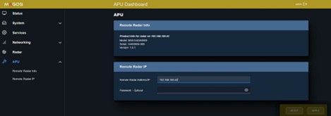
When adding the sensor in MASS, use the APU IP address rather than the radar's direct IP address.
MASS Installation
Run the MASS setup file. For further information and instructions consult with the “MASS User Guide” available for download in the “Documentation Tab”.
After installation you will be required to activate the MASS software liscense that was generated for you. Follow the instructions in the email you received to activate the license.
Stay in touch with Magos Support
| Region | Phone | |
|---|---|---|
| General | [email protected] | +972 55-881-1901 +972 50 603 6520 (messages only) |
| North America | [email protected] | +1 973-763-9597 (option 3) |
| LATAM | [email protected] | +52 55 2134 0800 (messages only) |
Physical installation guidelines
An ideal installation will be an open field with no obstacles and clear line-of-sight to targets; however, installation sites are not always ideal. When choosing a mounting location for the AR-Series Sensor, the goal is to optimize detection while minimizing the potential for false targets. It is highly recommended to conduct a site survey to identify the optimal position prior to installation. A site survey provides an opportunity to confirm coverage and mounting location with the customer prior to installing poles, power, and communication.
Follow the guidelines in this booklet for optimizing your radar performance.
The guidelines in this section are designed to optimize sensor performance. However, it is difficult to fully predict radar performance as it highly depends on monitored terrain. Performance can only be verified after positioning the sensor and monitoring its output. A new location should be considered if performance is not satisfactory within the area of interest.
Magos radar sensors are intended for outdoor use only and should be installed in restricted access areas such that only certified technicians or service personnel can access them.
Prcoessing Unit
Place the processing unit on the same switch as the radar as communication bandwidth between them is high and this will reduce load from the entire network. The processing unit is not IP67 waterproof and should be installed in a weather- proof cabinet/location. If installed in a non-air-conditioned field box, ensure the field box includes a fan with minimal airflow of 1m/s
Radar
Orientation
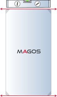
Sensor front should be pointed to the middle of the desired coverage area. Recommended tilt angle is 30 degrees above horizon as illustrated. Use a digital level to ensure proper positioning.
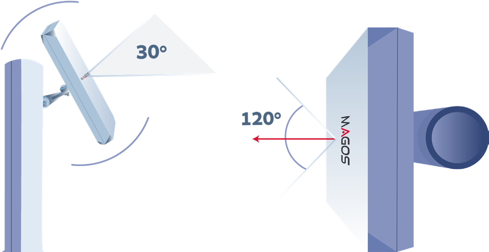
Use a digital level to ensure proper positioning. Make sure “roll” angle of the sensor is zero and that its “width” is parallel to the ground as illustrated:
Installation Height
There’s no minimum/maximum requirement on installation height. Choose ideal height in terms of line of sight.
Environment
As always with radars it is best to avoid high cluttered areas and large metal objects.
Do not place the radar where there are large metal objects (electricity poles, rails, poles) directly in in front of it or in its vicinity, as these act as reflectors and will lead to inaccurate detections.
Do not place the radar in the immediate vicinity of high traffic areas like highways, busy roads, or crowded walk-ways as these will generate “clutter” and lead to reduced performance.
Site survey checklist
Click here to download the Site Survey Checklist:
- The protected area is well defined and potential threat approachpaths are known.
- There is an obstacle free, clear line-of-sight to all areas of interest.
- Approach vectors were considered when considering maximum detection range. Reduced range is expected for tangent targets.
- Mitigate clutter – ensure that sensor coverage area includes as little clutter generators as possible, avoid busy roads, dense vegetation etc
- Avoid large metallic objects in the vicinity of the sensor. Ensure that there are no large poles/high fences directly in front of it, and it is located away from large vehicle traffic areas.
- LAN and power are available at the installation location.
- PTZ cameras (if used for visual verification of targets) have clear line of sight to the entire protected area.
- If any wireless point-to-point or similar devices are used, ensure coexistence with the radar’s operating frequency band