SR Series
Thank you for purchasing the Magos SR Series Sensor. This guide is designed to assist first-time users to connect and operate the SR- series radar sensor. It is strongly recommended to carefully read and review the entire SR- series User Manual as well as the MASS User Guide (if purchased) for safe and proper operation of the sensor.
SW INSTALLATION & CONFIGURATION
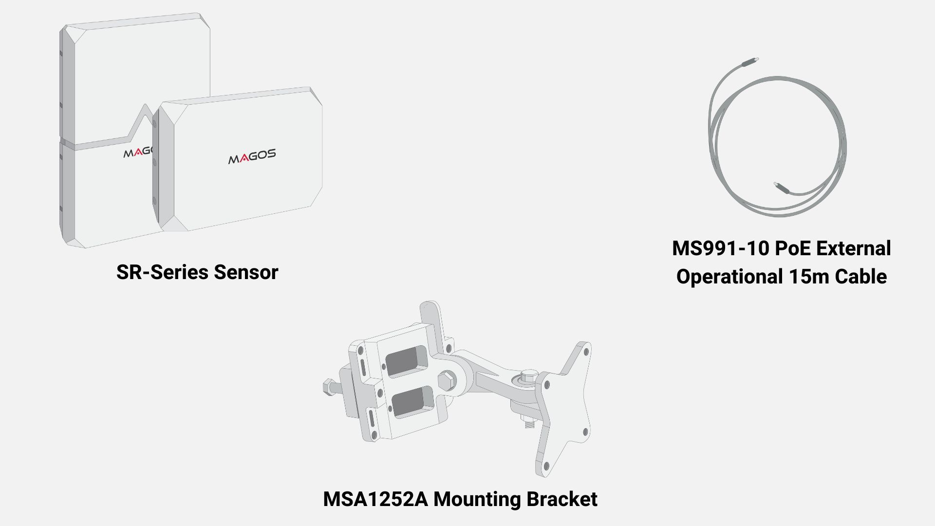
VISUALLY INSPECT THE CONTENTS OF THE PACKAGE
Ensure that the package contents matches your order and that no physical damage has occurred to any of the supplied products during transportation.
Connect the cable to the sensor
Follow the mating guide key on both sides as illustrated:
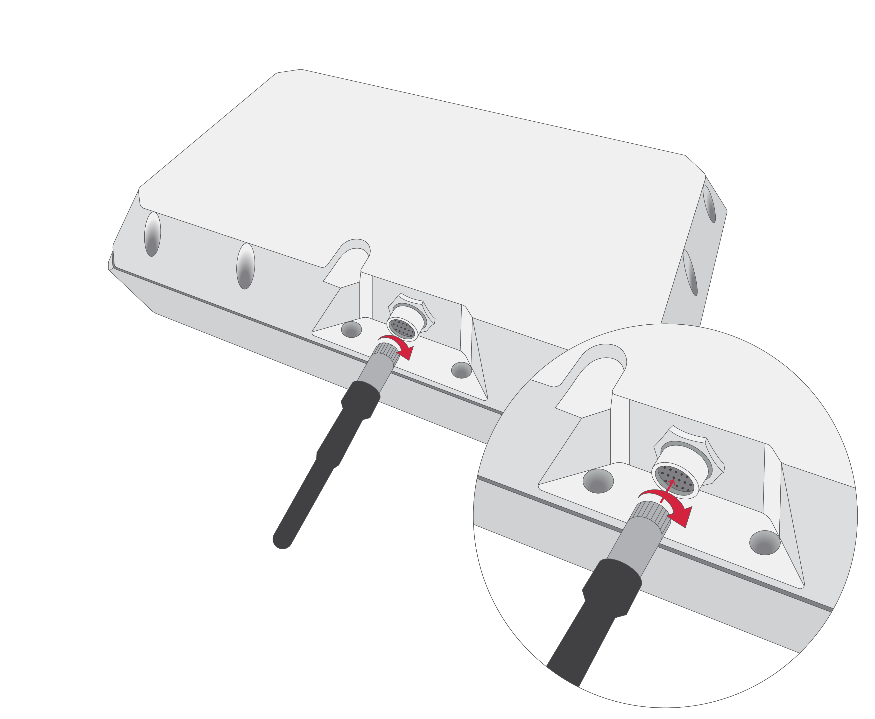
THE WARRANTY DOES NOT COVER WATER DAMAGE CAUSED TO THE CONNECTOR. TO AVOID SUCH DAMAGE, THE CAP MUST BE ATTACHED WHENEVER A CABLE IS NOT PLUGGED IN WHETHER USING THE CABLE OR THE CAP, ENSURE THAT THEY ARE SECURELY CONNECTED BY TWISTING THEM UNTIL FIRMLY LOCKED.
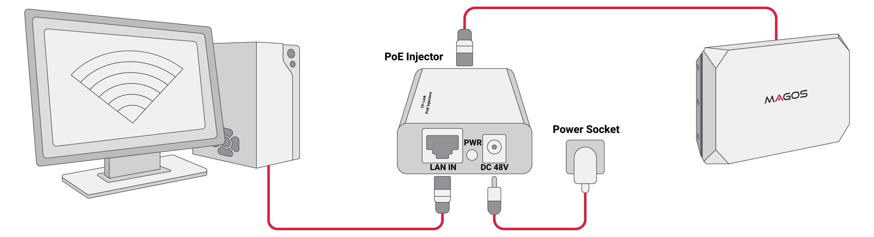
Connect the sensor to a PC
Use a PC or Laptop running Windows 7 OS or higher. Review minimum system requirement at Magos' Partner Portal under the documentation tab.
There are 3 available options:
-
Using a PoE injector connect the radar directly to a PC
-
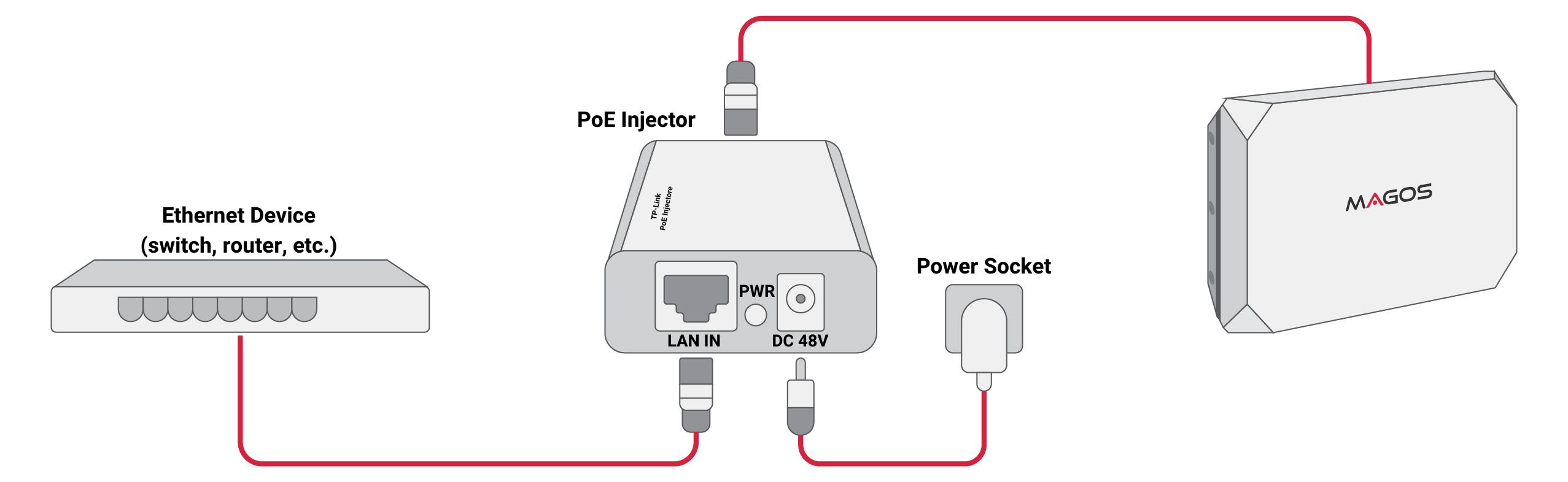
PoE Injector + Regular Switch
-
PoE Switch
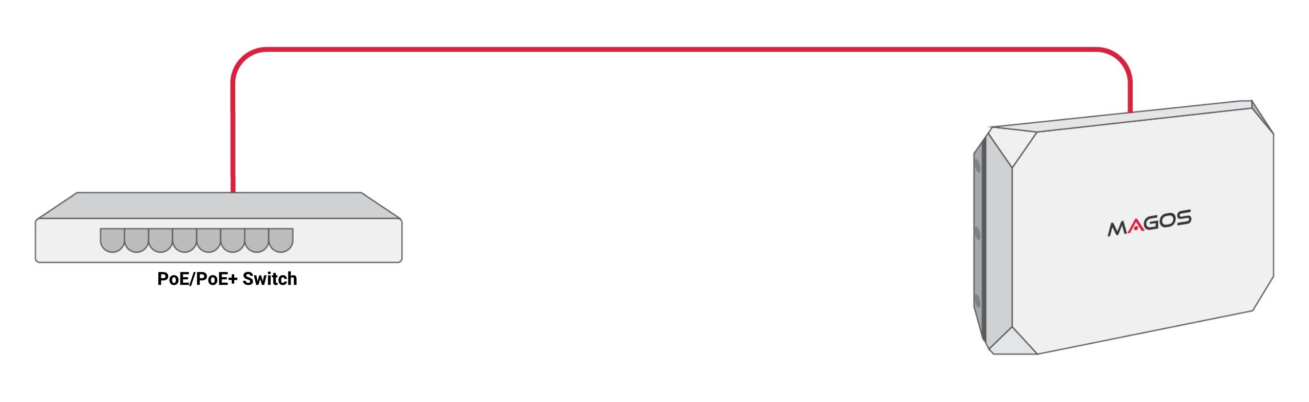
THE RADAR SENSOR MUST BE CONNECTED ONLY TO A CERTIFIED POE INJECTOR CONFORMING TO IEEE 802.3AT TYPE 1 (IEEE902.3AF) AND TYPE 2. THE INJECTOR SHOULD BE SUITABLE FOR CONNECTING TO OUTDOOR EQUIPMENT. FOR SAFETY REASONS, PRIOR TO HANDLING THE RADAR SENSOR ITSELF DISCONNECT THE CABLE FROM THE POE INJECTOR.
Download software from our Partners Portal
Visit our Partner Portal.You will be required to login using the credentials you have received from [email protected]. Browse to the “Software” tab and download the Radar Manager Application as well as the MASS application (if purchased) from the “Downloads” tab.
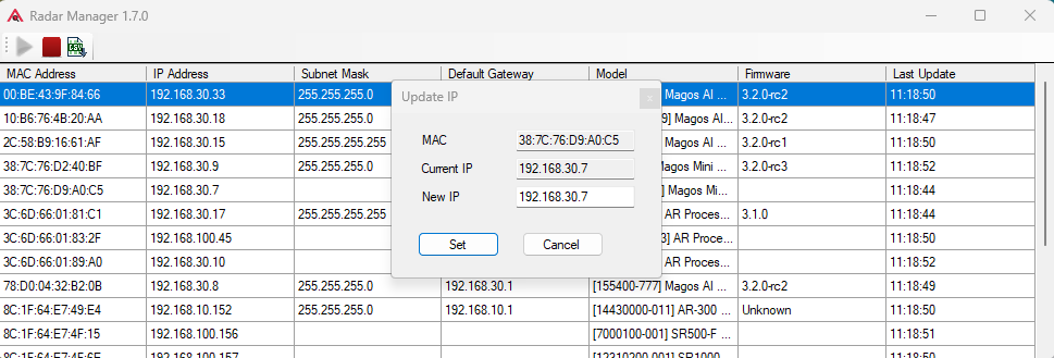
Assign IP to the sensor
Option 1: Use the radar manager application to assign a new IP address to the sensor: To change IP, right click on the current IP address reported, and choose “Assign IP”. The computer and the sensor must be in the same subnet mask, otherwise they will not communicate.
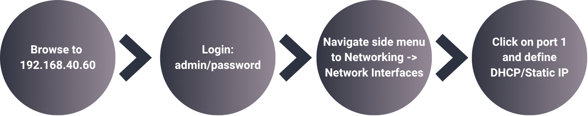
Option 2: SR-Series models also have a web-based dashboard. You can access the radar's IP address using any web browser. The default IP address is 192.168.40.50, username: admin, default password: password.
Make sure that the PC running the web browser and connected to the radar is in the same subnet mask:
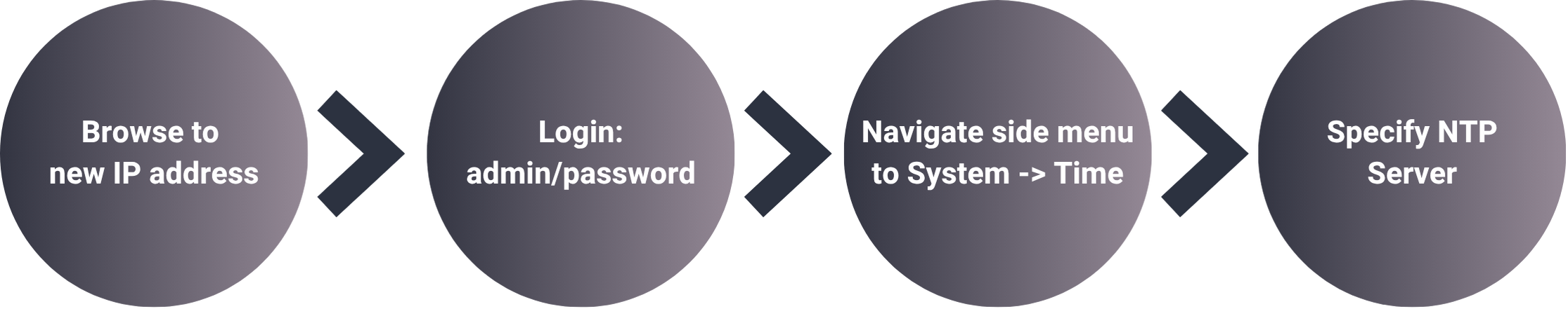
Set an NTP Server for the radar
After setting the new IP address, it is important to set an NTP server for the radar to ensure it operates properly with MASS. To do so, log in to the radar dashboard again in its new IP and set the IP address of the local NTP server:
MASS INSTALLATION
Run the MASS setup file. For further information and instructions consult with the “MASS User Guide” available for download in the “Documentation Tab” at our Partner Portal
AFTER INSTALLATION YOU WILL BE REQUIRED TO ACTIVATE THE MASS SOFTWARE LICENSE THAT WAS GENERATED FOR YOU. FOLLOW THE INSTRUCTIONS IN THE E-MAIL YOU RECEIVED TO ACTIVATE THE LICENSE.
Stay in touch with [email protected]
We recommend that you send us package order confirmation as well as any other questions you might have (mismatching package content, missing Partner Portal credentials etc.).
PHYSICAL INSTALLATION GUIDELINES
1. How & Where to Install
An ideal installation will be an open field with no obstacles and clear line-of-sight to targets; however, installation sites are not always ideal. When choosing a mounting location for the SR-Series Sensor, the goal is to optimize detection while minimizing the potential for false targets. It is highly recommended to conduct a site survey to identify the optimal position prior to installation. A site survey provides an opportunity to confirm coverage and mounting location with the customer prior to installing poles, power, and communication.
Follow the guidelines in this booklet to optimize your radar performance.
THE GUIDELINES IN THIS SECTION ARE DESIGNED TO OPTIMIZE SENSOR PERFORMANCE. HOWEVER, IT IS DIFFICULT TO FULLY PREDICT RADAR PERFORMANCE AS IT HIGHLY DEPENDS ON MONITORED TERRAIN. PERFORMANCE CAN ONLY BE VERIFIED AFTER POSITIONING THE SENSOR AND MONITORING ITS OUTPUT. A NEW LOCATION SHOULD BE CONSIDERED IF PERFORMANCE IS NOT SATISFACTORY WITHIN THE AREA OF INTEREST
MAGOS RADAR SENSORS ARE INTENDED FOR OUTDOOR USE ONLY, AND SHOULD BE INSTALLED IN RESTRICTED ACCESS AREAS SUCH THAT ONLY CERTIFIED TECHNICIANS/SERVICE-PERSONNEL CAN ACCESS THEM.
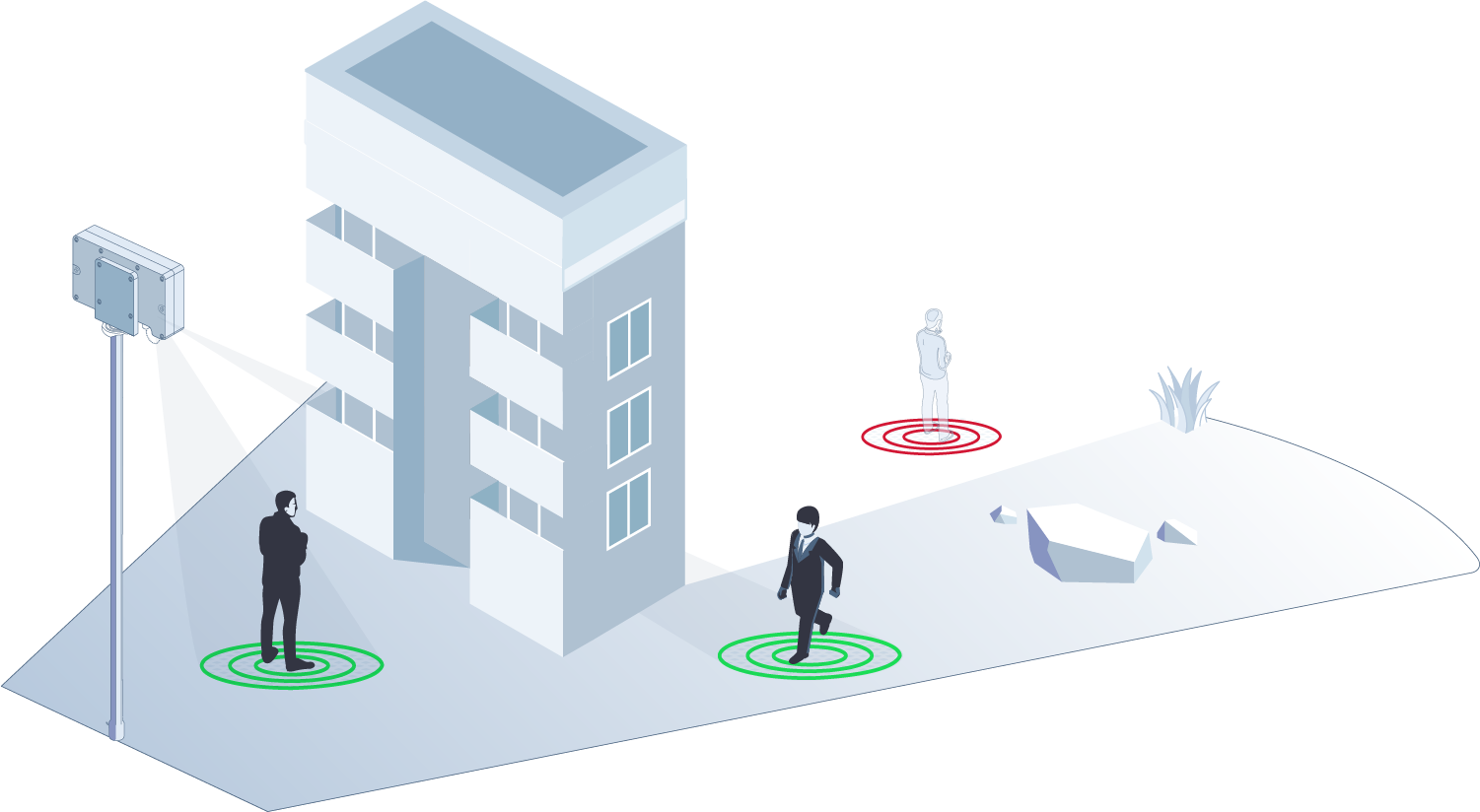
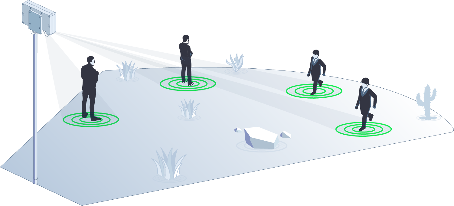
2. Line-of-Sight
You should start with a clear definition of the area you want to cover, identifying where potential targets/threats are expected to come from. Clear line of sight is required in order for the SR Sensor to maximize detection. Targets outside of the SR Sensor detection range will not be tracked.
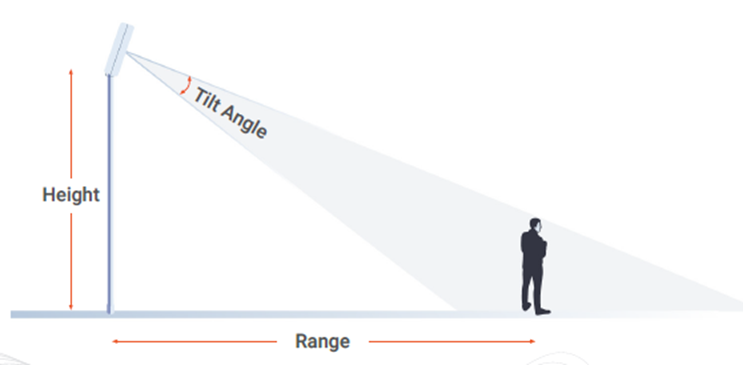
3. Installation Height
A good method for improving line of sight and sensor performance is increasing installation height. The following table summarizes recommended mounting heights per sensor.
| Sensor | Recommended Installation Height |
|---|---|
| SR-150 | 6m |
| SR-250 | 6m |
| SR-500 | 6m |
| SR-1000 | 9.5m |
For a full table consult with the SR-Series User Manual (available for download in the “Documentation” tab here.
When Installation height is much higher than the observed terrain level, the recommended practice is to tilt down the radar such that it is pointing at the maximum desired range of detection – as illustrated. This is subject to coverage areas and environment.
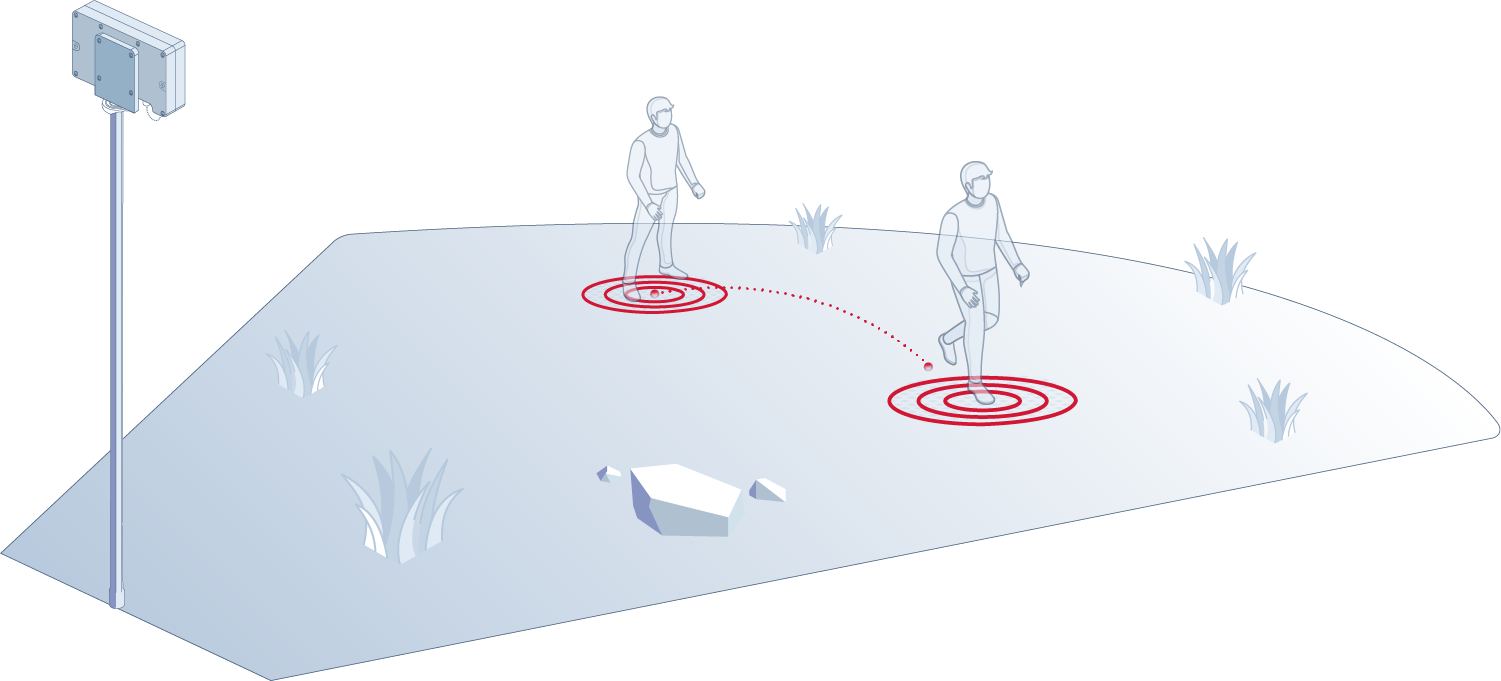
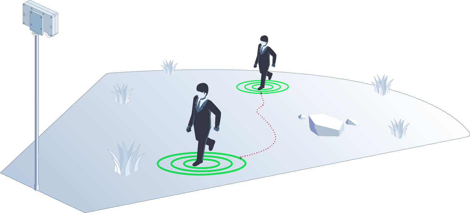
4. Tangent VS. Radial Movement
Doppler effect improves the detection performance of the radar by allowing it to differentiate between targets moving towards/away from it and static objects. However, “tangent” moving targets do not generate the Doppler effect and are less differentiable. Position the SR-Series sensors in such a way that potential threat vectors are as radial as possible. Otherwise, maximum reliable detection range is reduced.
5. Avoid Clutter
“Clutter” in terms of radar is any object that might generate background noise or detections that are not real threats.
Major clutter sources are:
- Large unkempt flora such as large dense bushes or weeds, especially in windy regions
- Busy roads rich with vehicle/human traffic
6. Metal Objects
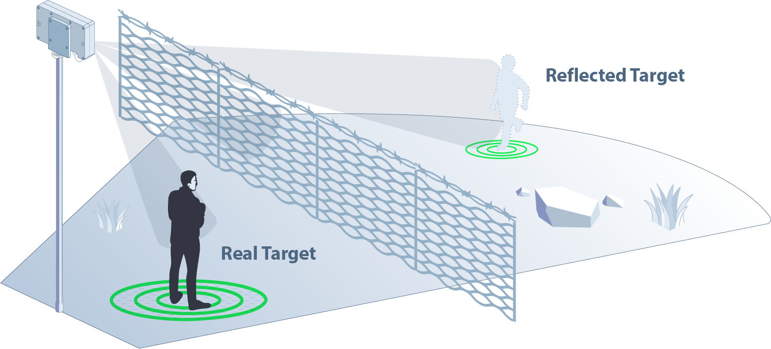
Avoid placing the radar in the vicinity of large static metallic objects: static objects such as large poles, fences, rails etc within the near vicinity of the radar might results in in-accurate target position measurement, and “ghost” targets created by real targets (even outside the stated coverage) reflecting off the metal object. Note that the “reflected” targets may also occur even if the metal object is not in the near vicinity of the radar.
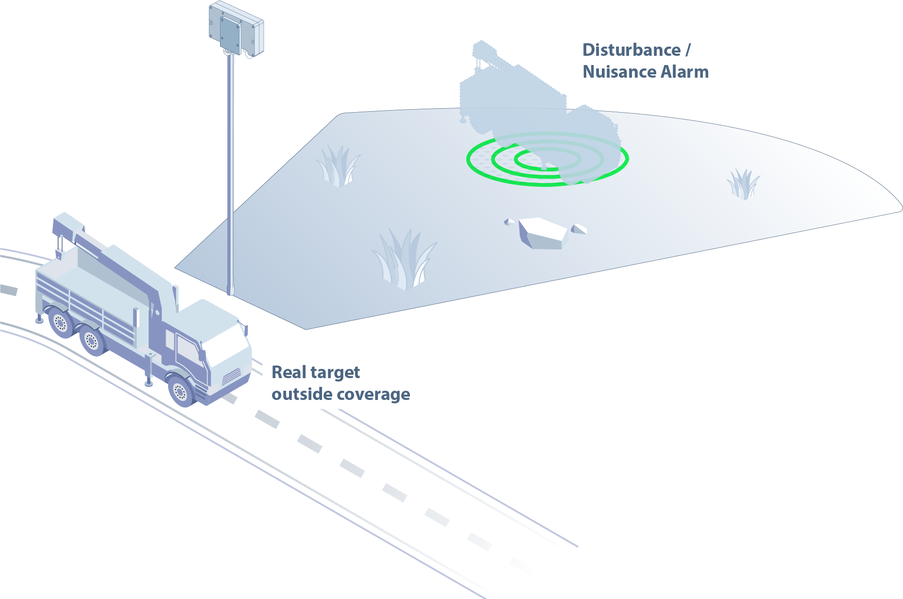
Avoid placing the radar in the vicinity of large moving metallic objects: trucks, cars, forklifts etc, as these might generate too much reflected signal and thus blind the radar and prevent it from observing additional targets. In addition, such large “targets” might even be picked-up outside the coverage zone of the radar and generate nuisance alarms within the coverage zone.
Additional pole mounting considerations
Magos radars are sensitive to the radial (back-and-forth) velocity of the radar itself. A radial velocity of 0.2 m/s or above will cause degradation in detection performance. Hence, the pole mount and the pole itself should be planned to support minimal vibration speeds even under strong wind conditions. For more information, consult with the Magos knowledge center or support team:
| Region | Phone | |
|---|---|---|
| General | [email protected] | +972 55-881-1901 +972 50 603 6520 (messages only) |
| North America | [email protected] | +1 973-763-9597 (option 3) |
| LATAM | [email protected] | +52 55 2134 0800 (messages only) |
Site survey checklist
Click here to download the Site Survey Checklist:
- The protected area is well defined and potential threat approachpaths are known.
- There is an obstacle free, clear line-of-sight to all areas of interest.
- Approach vectors were considered when considering maximum detection range. Reduced range is expected for tangent targets.
- Mitigate clutter – ensure that sensor coverage area includes as little clutter generators as possible, avoid busy roads, dense vegetation etc
- Avoid large metallic objects in the vicinity of the sensor. Ensure that there are no large poles/high fences directly in front of it, and it is located away from large vehicle traffic areas.
- LAN and power are available at the installation location.
- PTZ cameras (if used for visual verification of targets) have clear line of sight to the entire protected area.
- If any wireless point-to-point or similar devices are used, ensure coexistence with the radar’s operating frequency band